Revolutionary Automated Food Machines
-
Call Us Today
+1 (646) 934 8634
-
Working Hours
Mon - Fri: 9 am to 6 pm
-
1951 Grant Street
Hollywood, FL 33020
Measurement is the fundamental key to determining what can be improved.
If you want to know how you can make your company more productive and environmentally friendly, do not hesitate to contact us.
Leak detection
It is performed by means of an ultrasonic device and marked on a label, to keep track of leaks.
Information obtained:
– List of the leaks found.
– Identification of each leak site.
– Quantitative report of leakage waste according to the plant’s installed compressed air capacity.
![]()
Air demand monitoring system
Elements designed to record the operation of the compressors, taking records of plant demand and air pressure in the system, with a moving average measurement, to obtain the actual curves of their behavior over time.
Information obtained:
– Percentage of compressors working according to demand.
– Measurement of compressed air demand in the plant.
– Behavior of the system pressure over time.
– Determination of the peak moments of air demand in the plant.
– Evaluation of the possible errors that can be committed at the moment of working the compressors, according to the demand.

Energy consumption measurement
An ammeter clamp is installed on the electrical connection to the motor of each compressor, which provides Power Factor, Active Three-phase Power and Apparent Power.
Information obtained:
– Power consumption in kW, both in load and no-load, during the time analyzed.

Measurement of the flow delivered by each compressor
Installation of the equipment at the compressor discharge, to obtain actual CFM at 100 PSIg pressure, as well as the three-phase Active Power.
Information obtained:
– Actual ACFM delivered by the compressor at 100 PSIg pressure.
– Actual three-phase Active Power of the compressor.

Flow measurement per machine
Direct measurement with rotameter or calculation of cylinder consumption, obtaining actual consumption in CFM of the machine or pneumatic element.
Information obtained:
– Actual consumption in CFM of the machine or pneumatic element.

Diagnosis of the state of the pneumatic network
A tour of the entire pneumatic installation analyzing each of the following aspects:
– Pressure.
– Air quality (filtering system according to ISO 8573:1).
– Inclination of the network.
– Connections.
– Line accessories.
– Condensation traps.
– Compressor room.
– Machine and service connections.
Information obtained:
– Once the above steps have been completed, the most important recommendations for improving the current network will be given
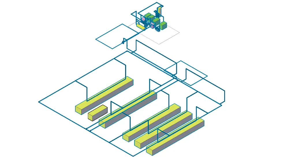
Redesign of network
Tour of the entire pneumatic installation, to analyze its condition and obtain:
– Calculation of the optimal diameter of the main network and the service network.
– Redesign of the pneumatic network, taking into account the real consumption of the plant, the pressure drops and the optimal distribution of connections and drains.
– Delivery of the new network plan, taking into account the technical recommendations. Correcting the deficiencies found in the current network, such as compressor room, connections, location of drains, network inclinations, among others.

